Flow
Flow
Flow menu provides designing and controlling the flows functions.
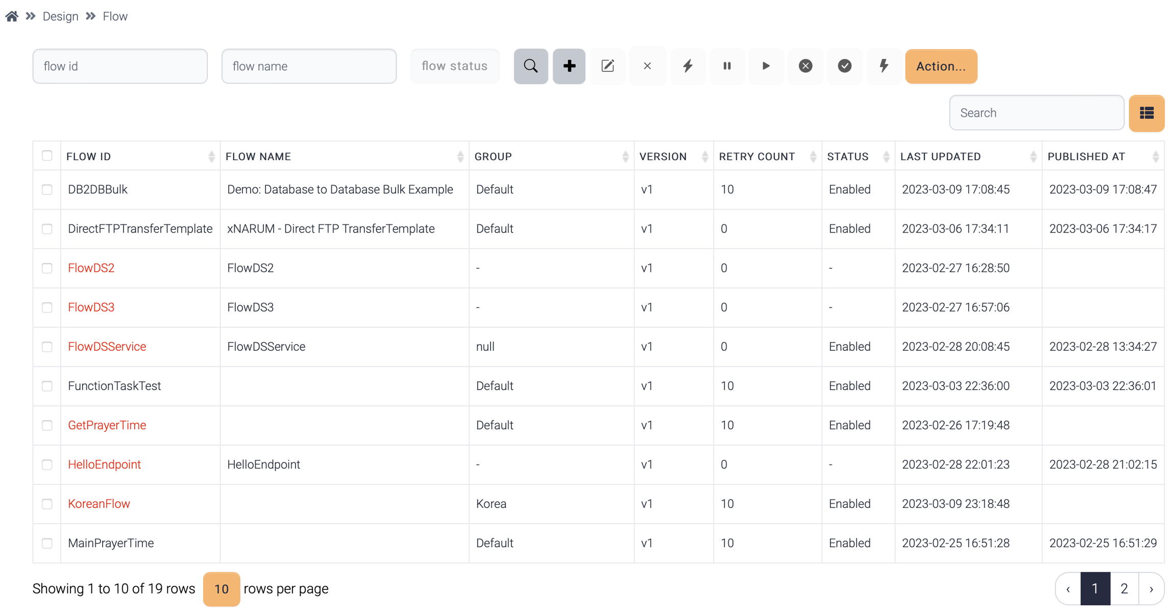
A flow generated by a normal user belongs to the group and this flow is not visible to the users of different groups. Likewise, system, data structure, field group, field are invisible to other groups.

Admin users can view to which groups the flows belong.
State
A flow can be executed only when enabled.
Enabled - default state when a flow is published.
Disabled - requests of disabled flow are discarded.
Paused - requests of paused flow are kept only when invoked asynchronously.
Operations
These are the available operations to the flows.
Name
Description
![]() Publish
Publish
Load selected flows to the cache. This operation asks to the instances to load flow information from database to cache.
![]() Enable
Enable
Enable the disabled flows. This change is published automatically.
![]() Disable
Disable
Disable the selected flows. This change is published automatically.
![]() Pause
Pause
Pause the selected flows. This change is published automatically.. Pause has effect only when the flow is invoked asynchronously.
![]() Runtime
Runtime
View runtime flow information. Each instance has its own cache in its own memory
![]() New From Template
New From Template
Create a new flow from the templates. The available templates are the followings:
DB to DB
DB to File
File to DB
File to File(With mapping)
File to File(Get and Put) - The file is stored in the local disk before sending to the target server
File to File(Transfer) - No local disk is used to store a temporary file
Export
Export the selected flows as json file
Import
Import flows from json file
Restore
Restore a flow from the backup
Execute(*)
Execute current flow manually.
Report(*)
Documentation about the flow is generated in word document(.docx).
Export(*)![]()
Export the flow design only. This function is used to copy flow design to another flow.
Import(*)![]()
Import the flow design only. This function is used to copy flow design to another flow.
(*) These operations are available inside flow designer.
Attributes
A flow has these attributes.
Common
Name
Description
Flow ID
Flow ID
Flow Name
Name of the flow
Flow Version
Flow version. v1 is assigned if not specified
Group
Application group. Default is assigned if not chosen.
If this flow is generated by a normal user, the group of that user is assigned.
Retry Count
Retry count. Max retry count is 100.
Notification
If checked, an email notification is sent when the flow failed.
Single Transaction
If checked, all the sql operations are committed once after all the steps are compete. This attribute can work when one database is used for entire flow.
Single Transaction
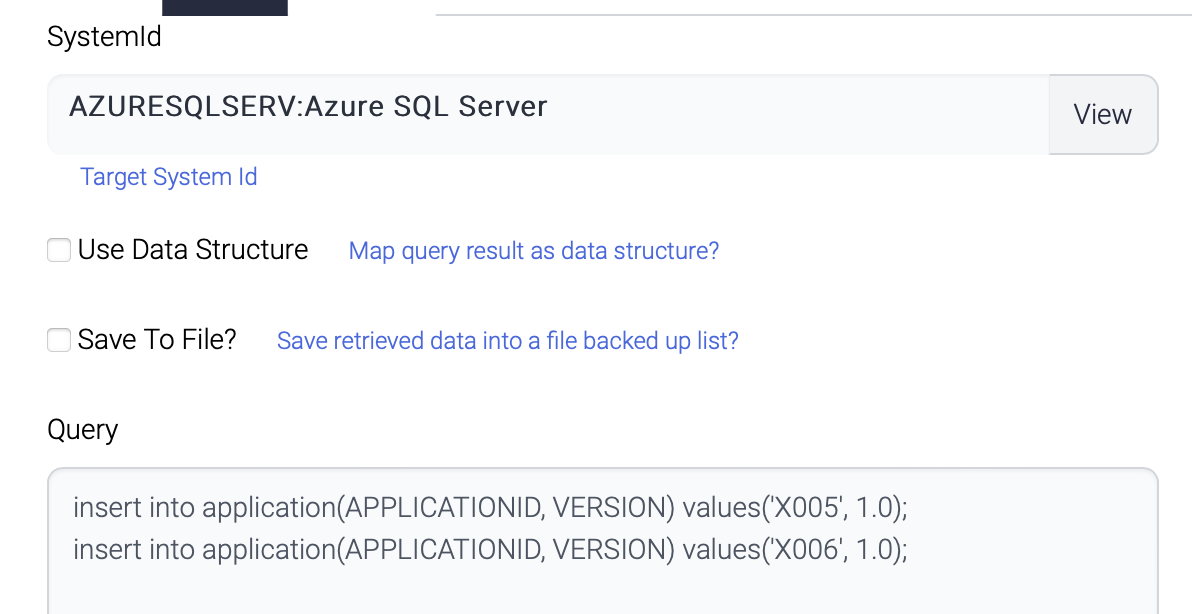
This flow inserts 4 records to the same table of the same database.

InsertFirst
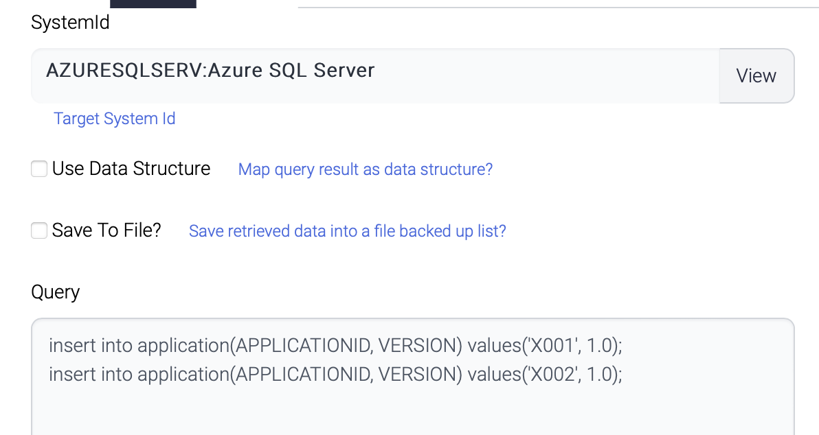
The first component inserts 2 records.
InsertSecond
The second component also inserts another 2 records to the same table.
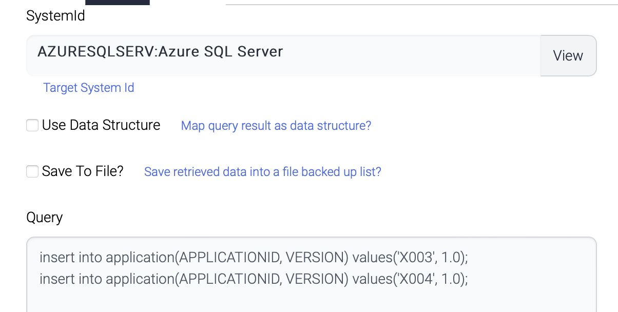
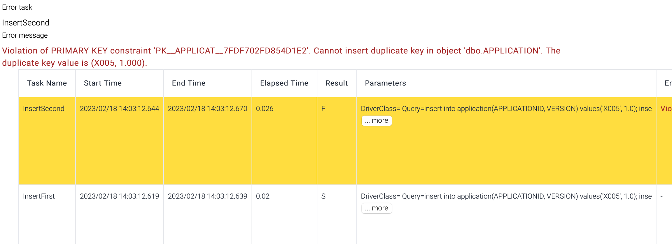
Both queries are not conflict and all the 4 records are inserted and committed.

But if the second component inserts the same records as the first one, all the records are rollbacked.
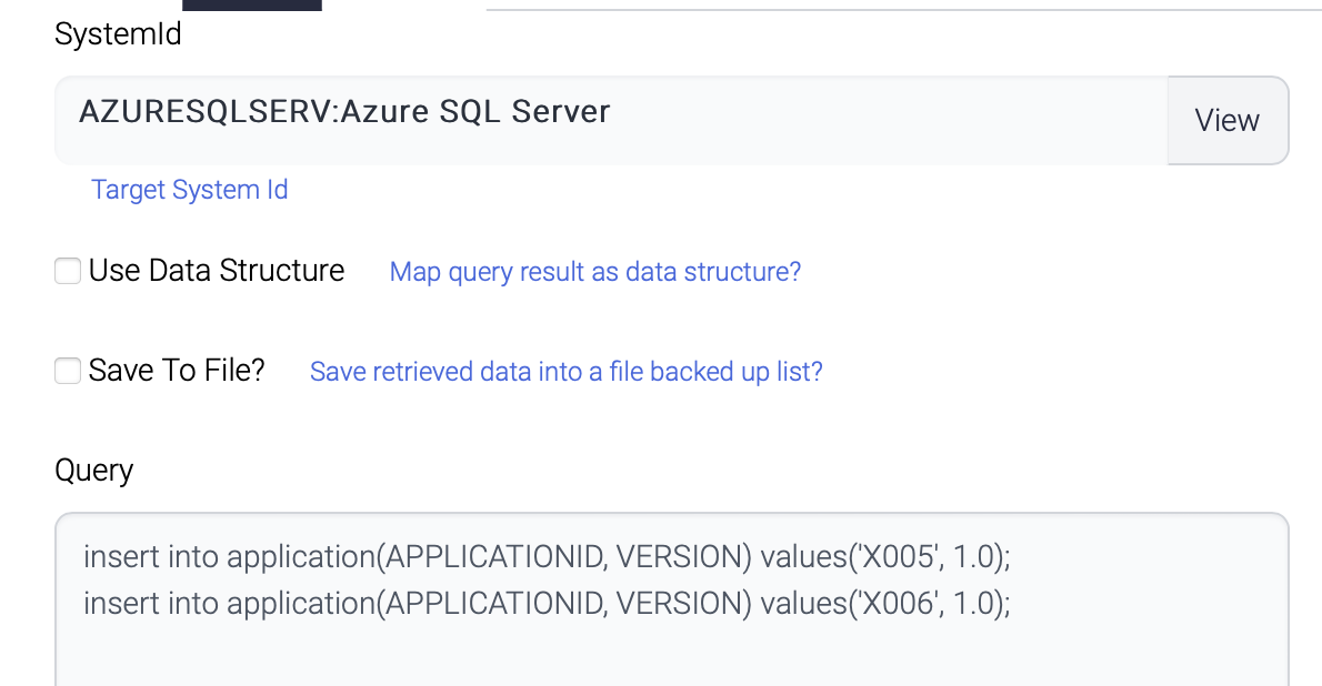
Transaction result shows the second step failed and no records are inserted.
Email notification
Email notification is configured per flow.
Name
Description
Subject
Email subject
Sender
Sender of this email
Receivers
Recipients of the email. Recipients are delimited with comma(,).
Host
SMPT Server
Port
SMTP Port
25 - default SMTP Port
465 - default TLS Port
Use ssl
If checked, TLS(SSL) is used to connect to SMTP server.
Password
Password of the sender
Policy
Once - email will be sent only once for the first failure.
Every time - email will be sent whenever the transaction fails.
Failure and recovery - email will be sent only for the first failure and the final success.
If the flow has retry count, email can be sent more than once.
Parameters
There are two types of parameters.
Input parameters
these are used to define global parameters in a flow.
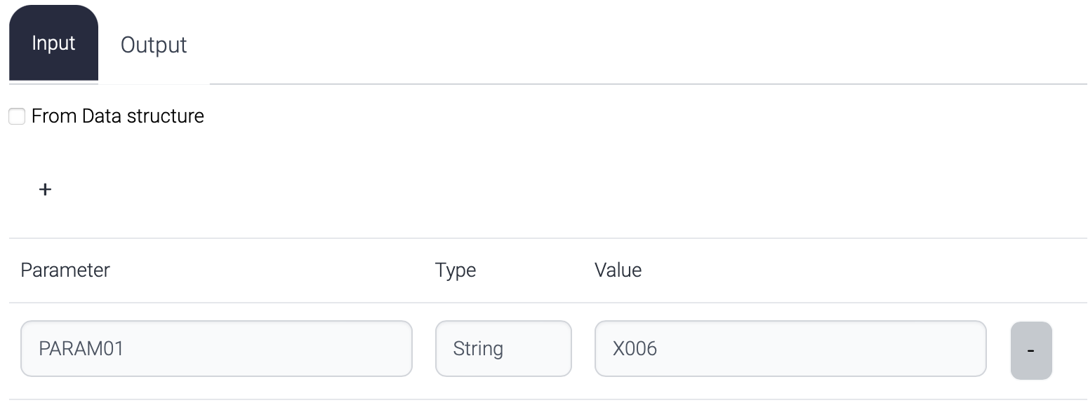
This parameter can be used in the flow like this.

Output parameters
These are used to generate response data.
If no output parameters are defined, default response from a flow is the output data for the last step.

The response data of the flow above consists of
Output data #1
Output data #2
Output data #3
But if any output parameter is defined, that parameter will be returned to the caller.
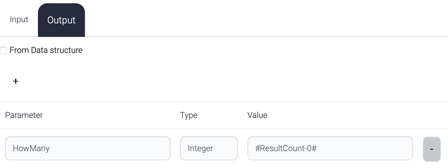
The response to the caller looks like this.
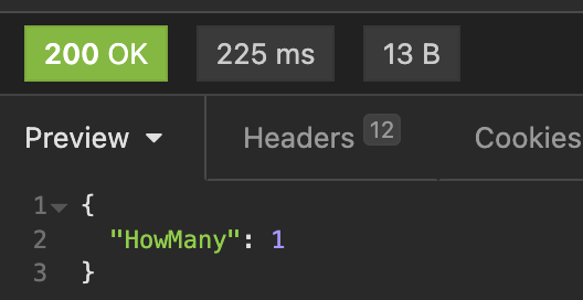
The priority of the response data is this.
ReturnComposer component in the flow.
Output parameter in the flow.
Output data of the final step in the flow.
ReturnComposer is used to pick up exact response data among the output data to the caller and this has the highest priority. If ReturnComposer does not exist, Output parameter is used. If no output parameter is defined, all the output data is returned to the caller.
Flow designer
Flow Designer is the main place to design and test the flow.
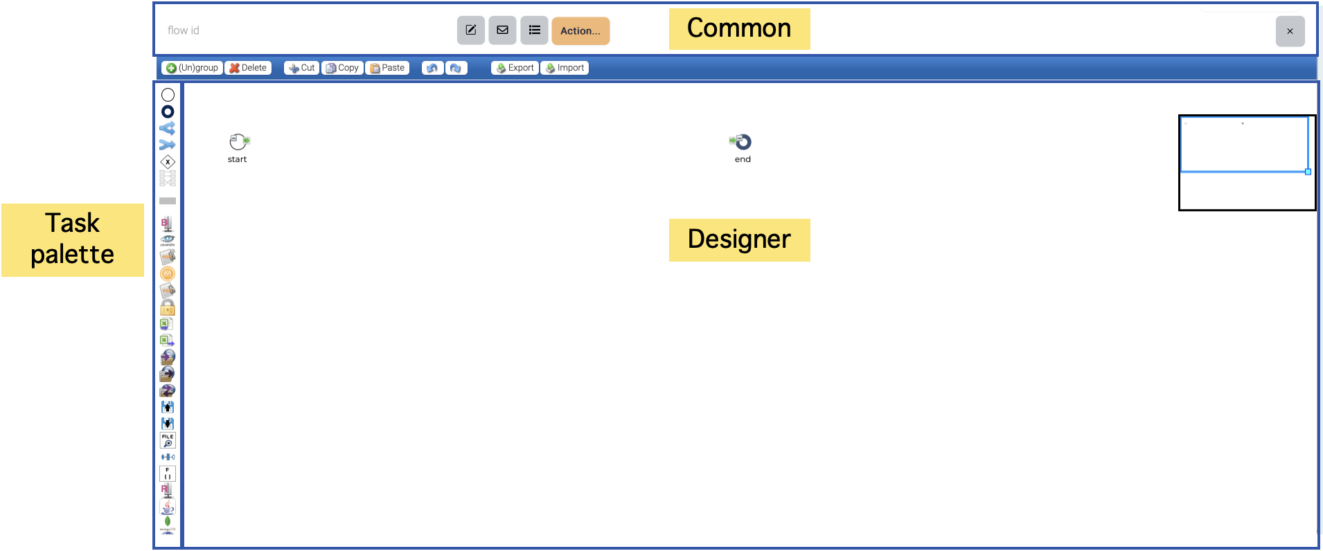
Designer consists of three parts. Top area is for common attributes of a flow ??? parameters, email notification and operations. Left area is for the plugins. The plugins have their own icons and just drag & drop the icons you want to use to the designer.
Designer area is where you design a flow with the plugins and control components.
Whenever a new flow is created, start and end nodes are automatically located.
Start node is the entry point of a flow and end node is the final step of a flow. But end node is not mandatory. If Flow controller cannot find the next step from the last executed step, Flow controller stops the execution.
Every function component in the task palette has one input port and two output ports.
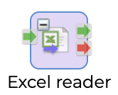
Input port is wired with one of the output ports of previous component.
There are two types of output ports. Green one means success and Red one means failure. Either output port is wired to the input port of another component. Both output port can be wired.
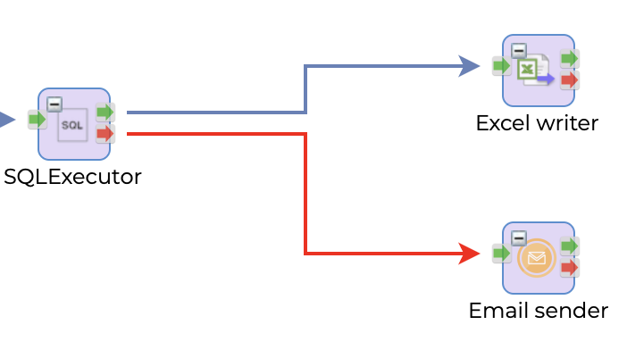
This picture shows if SQLExecutor succeeds, execute ExcelWriter otherwise EmailSender.
The red arrow is exception handling path and when this red arrow is wired, the execution of current step failed but treated as success and continue the execution.
To connect the nodes, click the output port and drag to the input port of the target node.
To delete the connection, click the connection and click ![]() .
.
To delete a node, click the node and click ![]() .
.
To copy a node, click the node and click ![]() and
and ![]()

In a typical flow, the execution starts from the start node and proceeds through each subsequent node until it reaches the last node before the end node. This last node represents the end of the execution, and the flow terminates successfully. However, in cases where a node fails and no exception arrow is wired, the failed node becomes the end of the execution. This means that the flow will not continue beyond the failed node, and any subsequent nodes will not be executed. It is important to note that in such cases, the flow does not terminate successfully, and appropriate error handling or exception handling mechanisms must be in place to ensure that the failure is properly handled.
Routing path
A flow can have routing paths. Routing path is used to determine the path of the flow.
Routing path can be specified with three types.
Part of path : /api/DB2DBBulk/v1?__RoutingPath=single
Request body
Parameter of schedule

This is the logic to determine the path.
All the paths from start node have routing path.
The request contains correct __RoutingPath - find the path which contains the routing path and execute.
The request contains invalid __RoutingPath - path is not found, and error is returned.
The request does not have __RoutingPath - path is not found, and error is returned.
Some of the paths from start node have routing path.
The request contains correct __RoutingPath - find the path which contains the routing path and execute.
The request contains invalid __RoutingPath - path is not found, and error is returned.
The request does not have __RoutingPath - the last path from the start node is chosen and executed.
Task
A task node is a key element in a flow that represents a specific action or operation to be executed as part of the workflow. To configure a task node, simply double-click on the node to open the task configuration window. This window provides access to the various input and output attributes associated with the task, allowing you to define the behavior and parameters of the task as required for your workflow. Each task node is unique and will have its own set of input and output attributes that are specific to the task being performed. These attributes can be configured as needed to ensure that the task operates as intended within the context of the larger workflow. Proper configuration of task nodes is essential for creating effective and reliable workflows that can efficiently automate business processes and other critical operations.
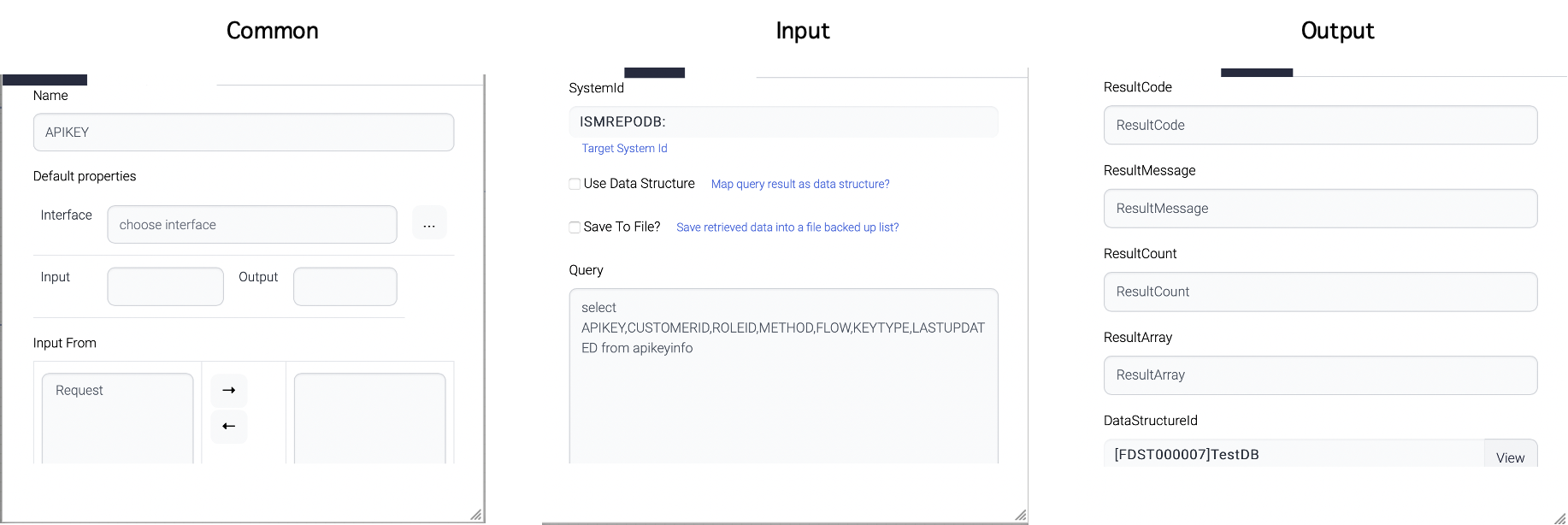
Common attributes are a set of attributes that are general for all tasks in a workflow. One of the example attribute is Name attribute. Most of the common attributes are maintained for backward-compatibility purposes.

One important common attribute is this - ignore previous success.
The "Ignore Previous Success" attribute is a useful feature in a workflow that is used during retry attempts. When a flow fails and has a retry count configured, the retry will typically resume from the point of failure and attempt to execute the failed step again.
However, when the "Ignore Previous Success" attribute is checked, the retry will execute the step again regardless of whether it was successful in previous attempts. This means that even if the previous execution of the step was successful, the retry will still attempt to execute the step again.
The "Ignore Previous Success" attribute can be useful in scenarios where the root cause of the failure is not clear, or when there is a suspicion that the previous success may have been due to an environmental factor or other variable that is no longer present. By forcing the retry to execute the step again, you can ensure that the failure is properly diagnosed and resolved, improving the overall reliability and effectiveness of your workflow.
Input attributes refer to the input arguments that are provided to a task within a workflow. These arguments can be defined as either constant values or as parameters that can be dynamically configured at runtime.
Constant input arguments are values that are set in advance and remain the same throughout the execution of the task. These arguments can include things like configuration values, default parameters, or other static values that are required for the task to function properly.
On the other hand, parameter input arguments are values that can be modified at runtime, either by the user or by the workflow itself. These arguments are typically defined as placeholders within the workflow, and their actual values are provided when the task is executed. This allows for greater flexibility and adaptability within the workflow, as parameters can be adjusted as needed to accommodate changing conditions or requirements.

The "Query" attribute of the screenshot above has query with parameters - #zone# and #Today#. These parameters come from the nodes which were previously executed or from the parent flows.
System
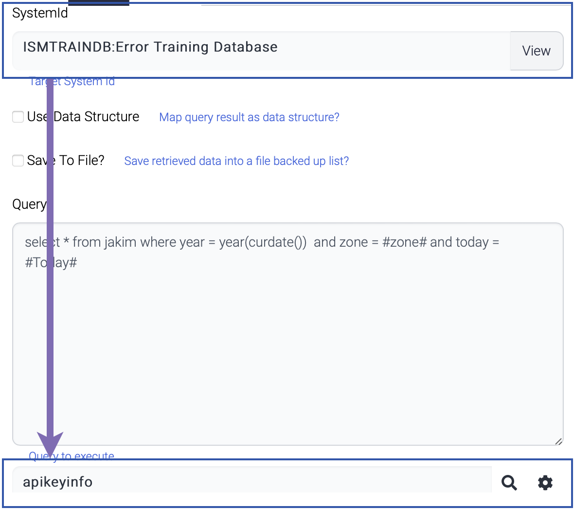
Some tasks require system information like database. Appropriate system information should be registered before the component is used.
For example, SQLExecutor component use system information to retrieve table list while the popup window is displayed.
Data structure
Data structure information is used in some components to generate output or read the input data against the predefined data structure.
One example of a component that relies on data structure information is Mapping, which uses predefined data structures to convert data from one format to another. By specifying the source and target data structures for the mapping, the component is able to automatically transform the data as needed, simplifying the mapping process and reducing the risk of errors or inconsistencies.
Another component that utilizes data structure information is ReturnComposer, which is responsible for constructing the response data that is returned from a workflow. By specifying the desired data structure for the response, the component is able to create a well-formed and consistent response object that meets the needs of downstream systems or applications.
Some components like FileValidator uses data structure information in the component and others link the output to data structure. The FileValidator component use data structure information to validate input data according to the predefined layout.

Publish
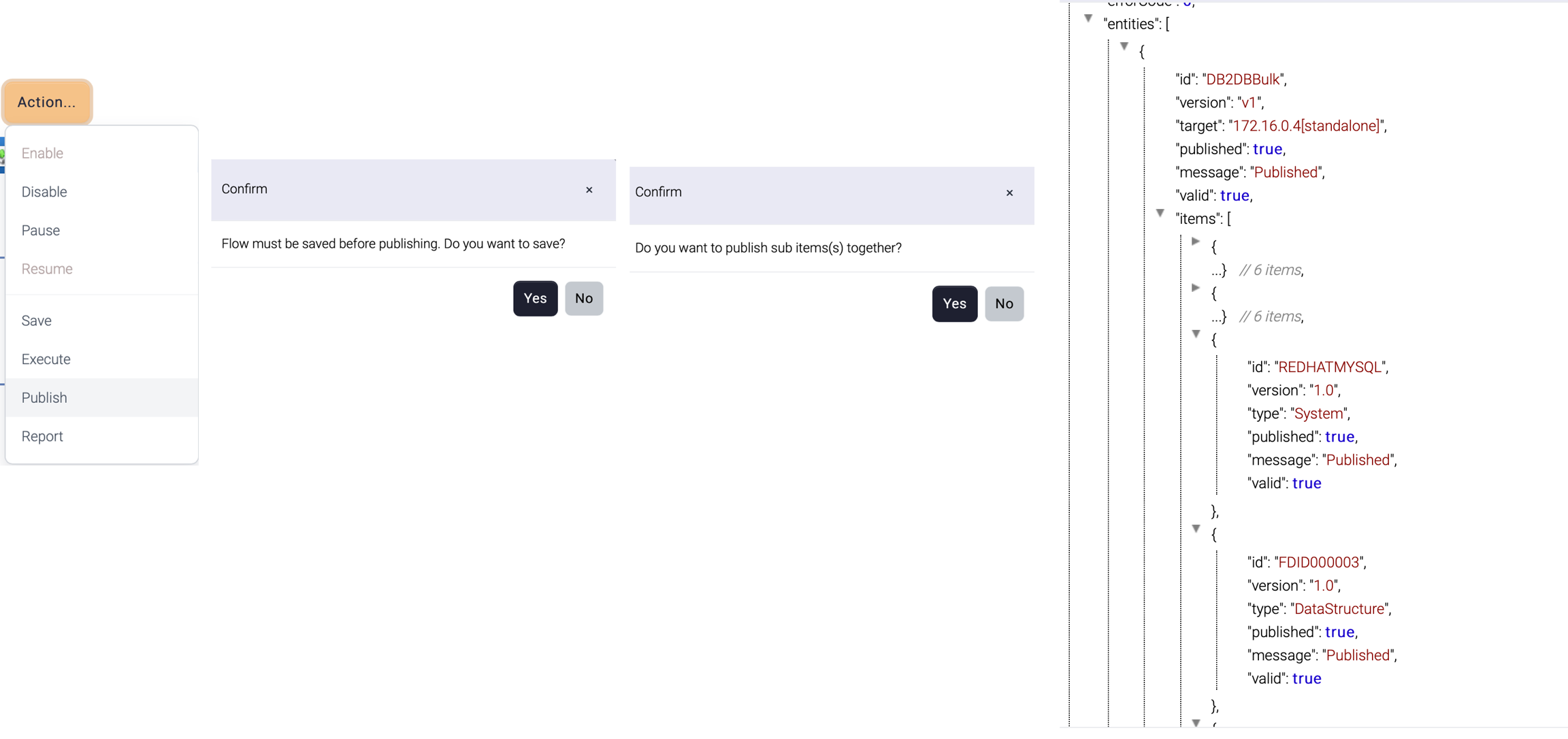
Once a flow design is complete, the flow should be published before used. When a flow is published, all the related items can be published together.
For example, the flow below contains three components

SQLExecutor
requires database information such as the server name, port, username, and password to establish a connection to the database.
generates result set according to the data structure for future mapping
Mapping
links the data structure information of both the input and output data.
SQLBatchExecutor
requires database information such as the server name, port, username, and password to establish a connection to the database.
requires data structure information to construct query according to the data structure
If the related items are not published, this flow cannot work correctly. So, the publish operation provides options to publish all items together.
Execute
During the design and development of a flow, it's available to test the flow to ensure that it functions as intended using Admin UI.
This flow is executed at a specific instance. If this flow contains input parameters, input parameters can be passed together.
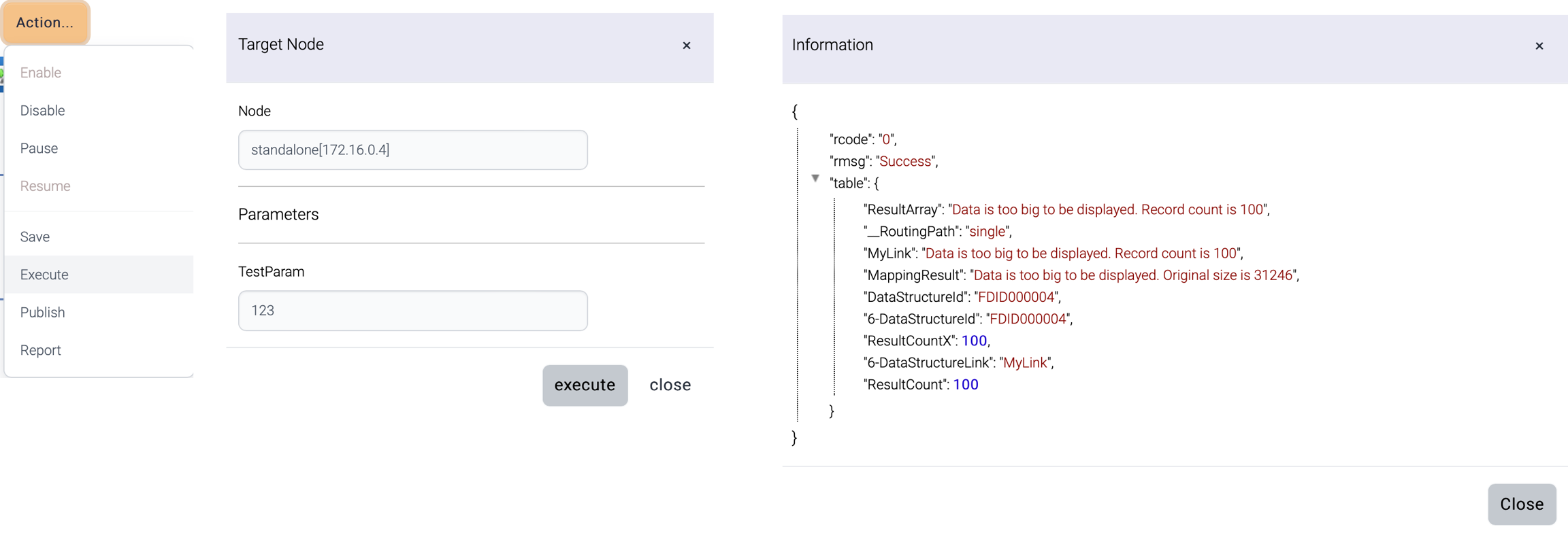
The target node list comes from the registered runtime nodes.
The result is displayed once the execution is complete.
Name
Description
rcode
Result code
0 = success
9 = error
rmsg
Error message
table
Response data
Report
Documentation for a flow is generated and downloaded as .docx document. Additional description about the flow can be added.
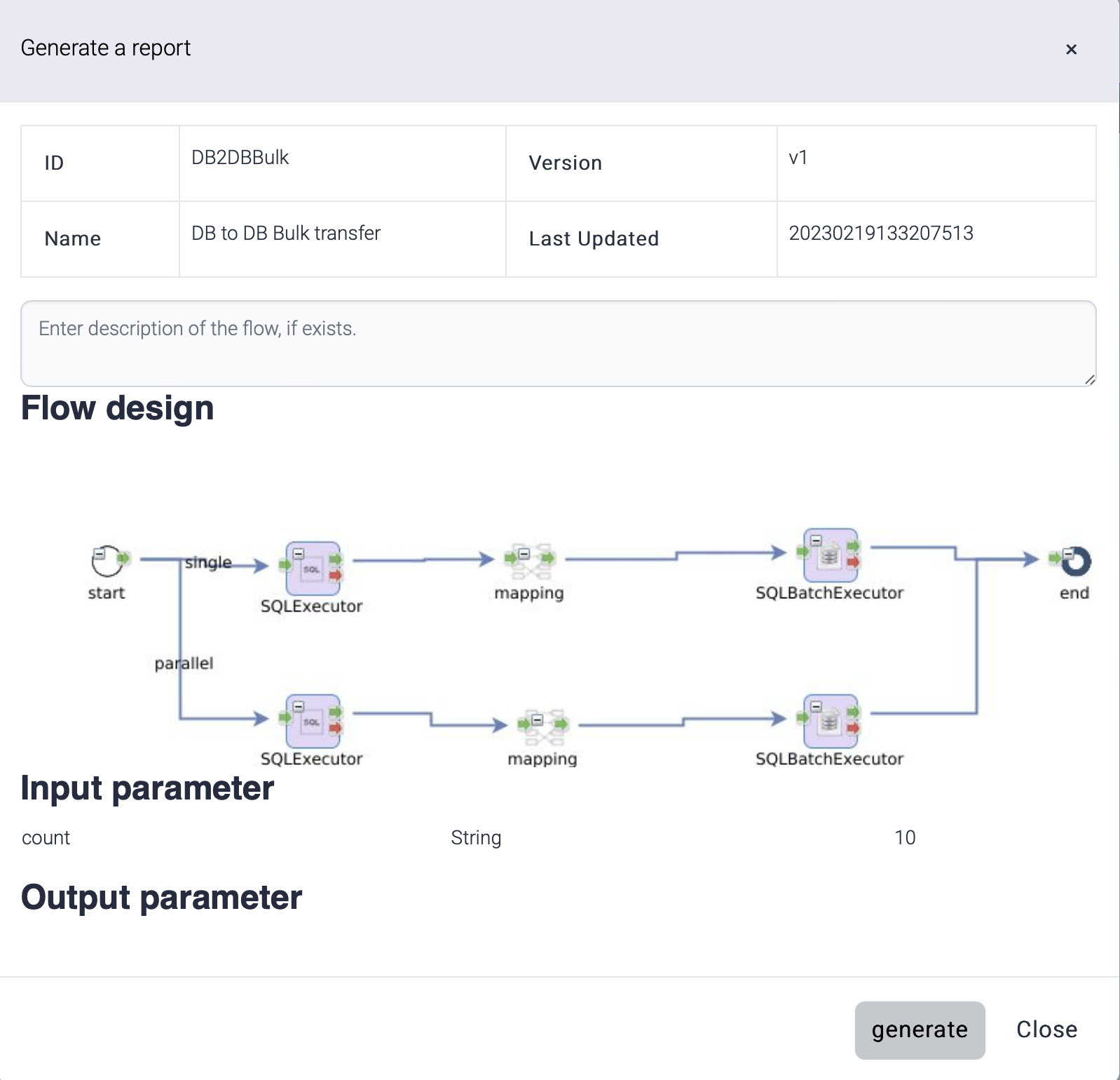
Generated report file is saved as this name.
Report-flow_id-yyyyMMdd.docx
The report contains the diagram of the flow and the properties of the tasks.
This report uses a template document (Flow-Report-Template.docx) and this template is located under data directory. If you want to use a different template, you can modify this document or set different template with this property. The property is configured in this file - install-dir/jetty-9.4.7/etc/xnarum.xml
Export/Import
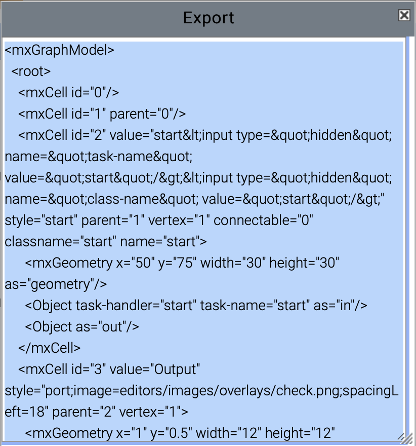
Click export (![]() ) button then a popup window with xml contents is displayed. Copy with Ctrl+A, Ctrl+C and close.
) button then a popup window with xml contents is displayed. Copy with Ctrl+A, Ctrl+C and close.
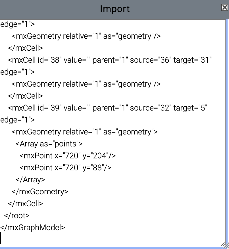
Create a new flow and click import (![]() ) button then a popup window is displayed. Paste the copied xml data into the dialog. Close the window then the imported flow design is displayed.
) button then a popup window is displayed. Paste the copied xml data into the dialog. Close the window then the imported flow design is displayed.
New flow from template
A flow can be created from a template. The available templates are these.
DB to DB
DB to File
File to DB
File to File(With mapping)
File to File(Get and Put) - The file is stored in the local disk before sending to the target server
File to File(Transfer) - No local disk is used to store a temporary file
When you click New from template button, a new popup is displayed.
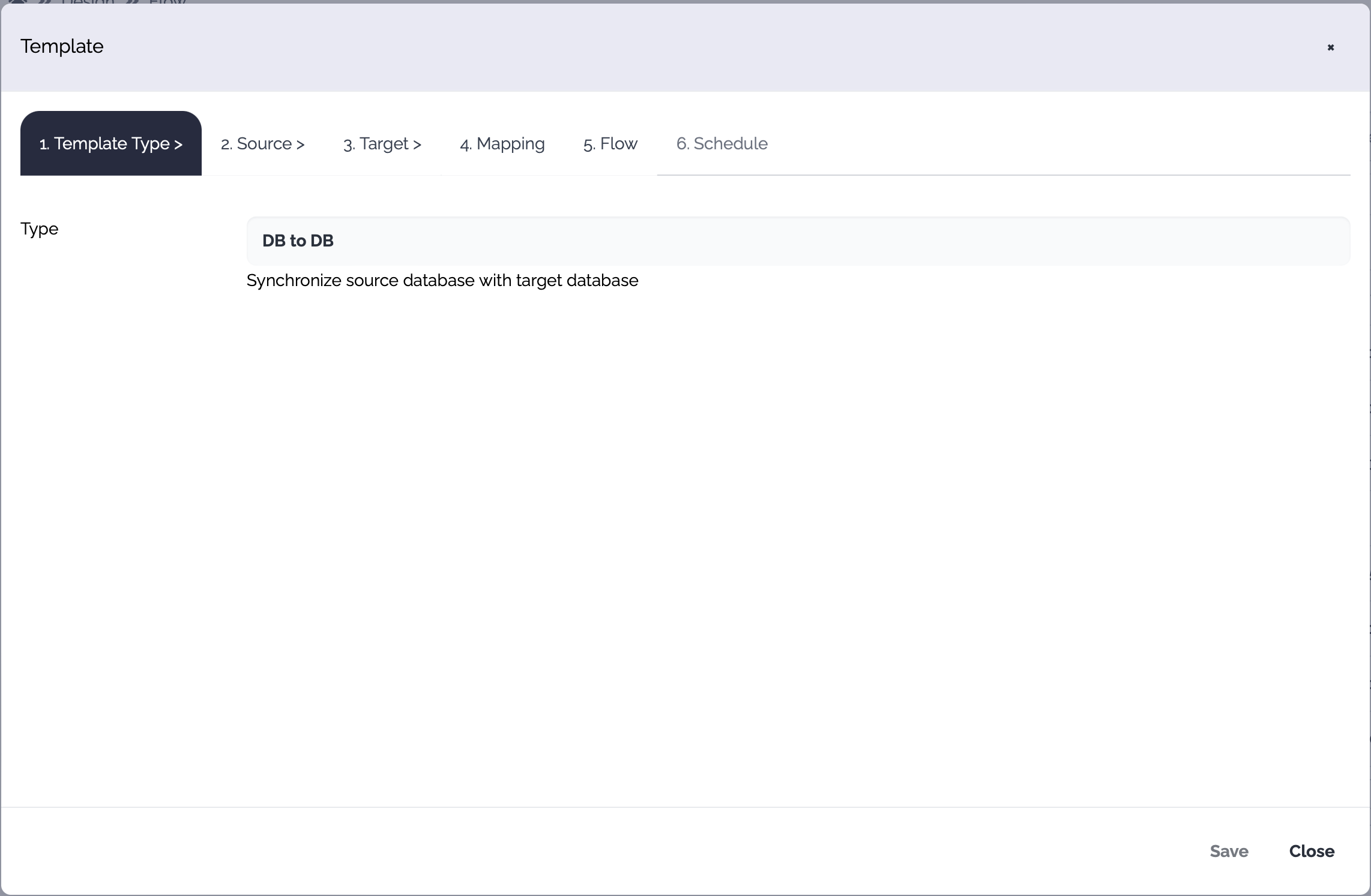
The template dialog consists of these tabs.
Template Type
Choose a template type
Source
The properties of the source system and operations are defined. A new system can be created through this flow generation and a new data structure can also be created.
Target
The properties of the target system and operations are defined. A new system can be created through this flow generation and a new data structure can also be created.
Mapping
Mapping between the input and output can be generated.
Flow
Default properties of the flow are defined.
Schedule
A schedule can be created but this schedule should be enabled manually later.
1. Template Type
Choose the template type

2. Source
Choose the source system and the operation
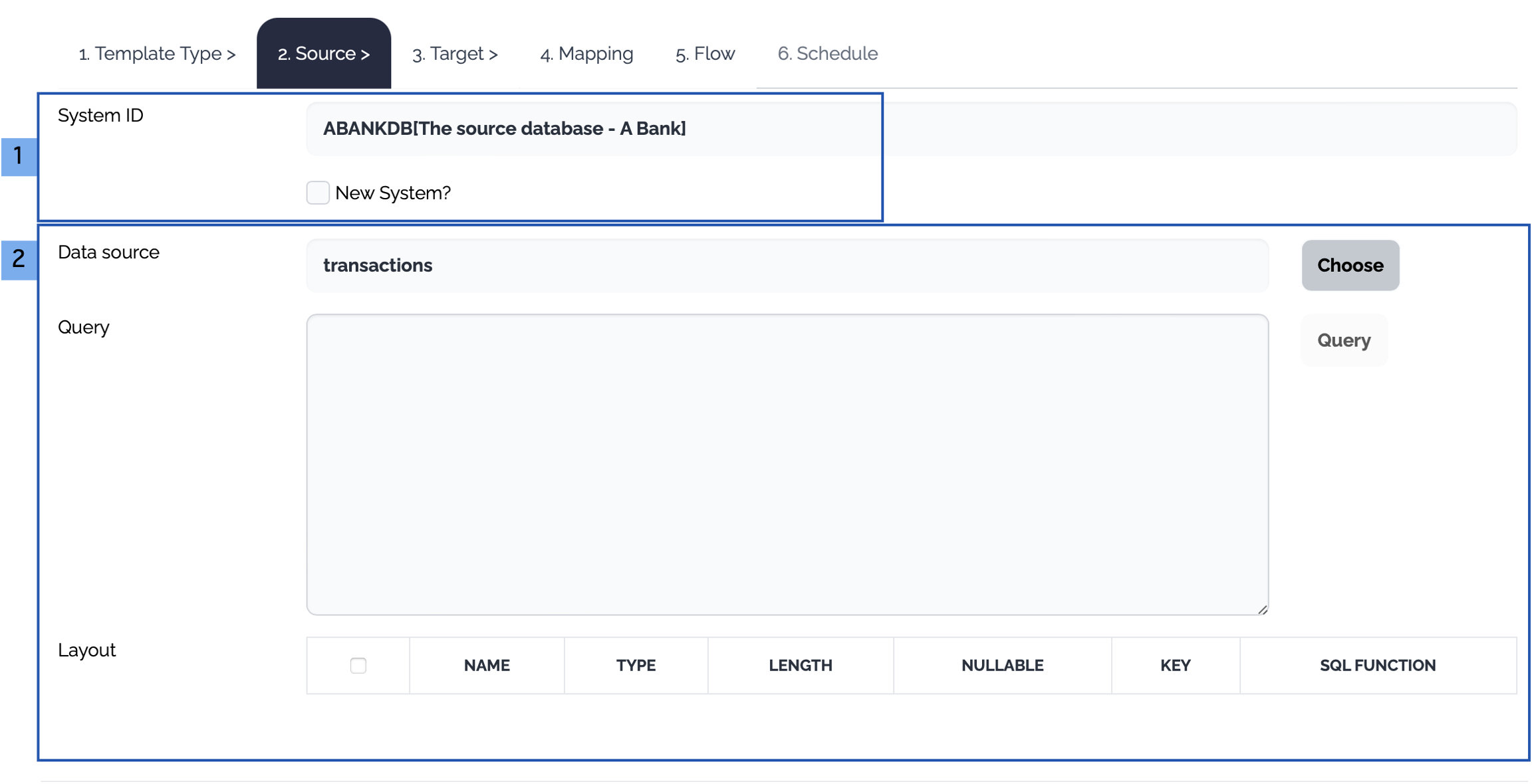
The source systems of the selected template type are displayed. Choose an existing system or click New System checkbox.
Database
PropertyTypeDescriptionID
Optional
System ID. If empty, a random system id is generated.
Name
Optional
System Name
Database Type
Mandatory
Mysql
Postgresql
SqlServer
Oracle
DB2
DB2AS400
Informix
Custom
Host
Mandatory
Database Host
Port
Mandatory
The listening port of the database
User
Mandatory
The user of the database
Password
Mandatory
The password of the user
Connection Pool Size
Optional
The maximum size of the connection pool
Validation Query
Optional
The query used to validate the connection
Connection String
Mandatory
The connection string used to connect to the database. If empty, a new connection string is generated automatically from the properties
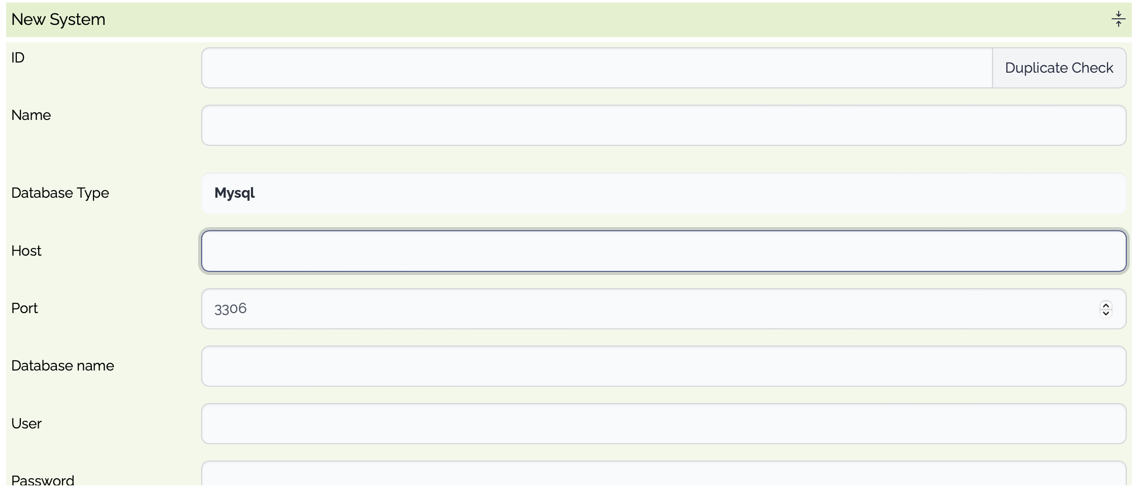
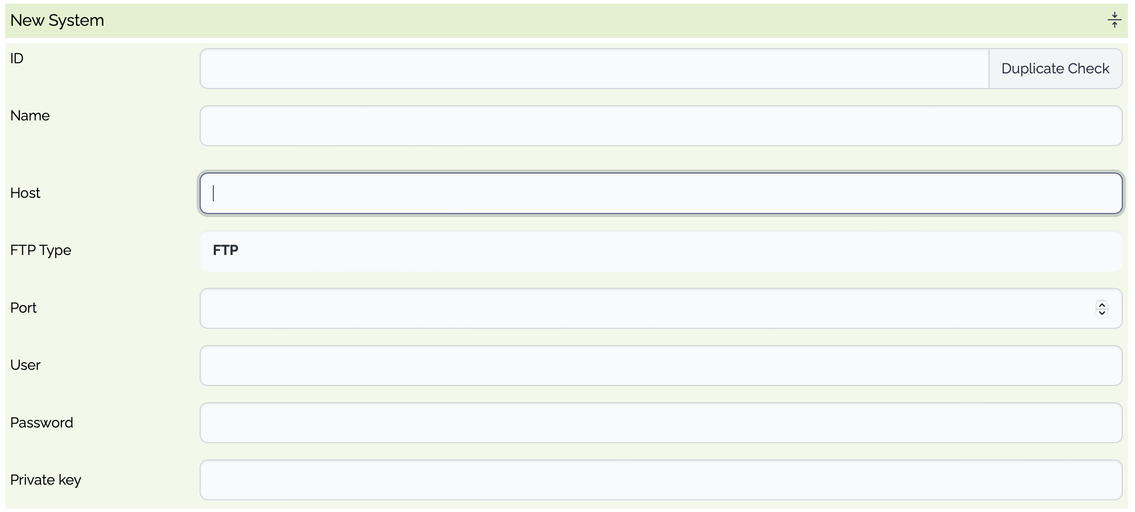
File
PropertyTypeDescriptionID
Optional
System ID. If empty, a random system id is generated.
Name
Optional
System Name
Type
Mandatory
File Transfer Type
sFTP
SCP
FTPs
FTP
Host
Mandatory
File Host
Port
Mandatory
The listening port of the (s)FTP server
User
Mandatory
The user of the (s)FTP server
Password
Mandatory
The password of the user
Private Key
Optional
The private key of the user, if used
Passphrase
Optional
The passphrase to access the private key, if used
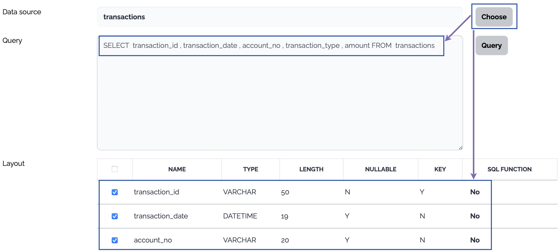
Define the operation on the source data
Database
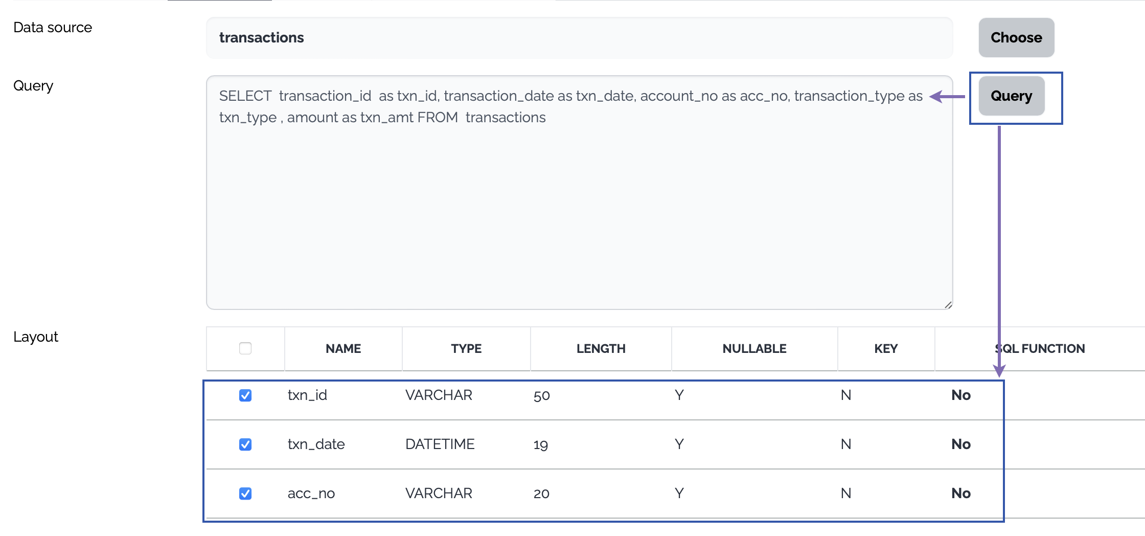
Click Choose button, a select query is generated from the layout of the selected table and the columns of the select query are displayed as a data structure.
Or type a query to select data from the source database and click Query button. The columns of the query are displayed as a data structure.
File
PropertyTypeDescriptionSource File Path
Mandatory
The path of the source file - directory
Source File Name
Optional
The name of the source file. Only one file is processed for the template types which involves the mapping.
If Source File Not Found?
Mandatory
The action when the source file is not found.
Throw Error
Ignore - If the template type requires mapping, an exception is thrown.
After Get Action
Mandatory
The action after the source file is collected.
Do Nothing
Backup - Move the source file to the backup directory of the remote server
Delete - Delete the source file from the remote server
Backup Path
Optional
The name of the backup directory of the remote server.
Output File Path
Mandatory
The local path where the source file(s) are stored.
Need Data Structure
Optional
If the template types involve mapping, this property must be checked, and a new data structure should be created accordingly.
Generation of the data structure of the file type
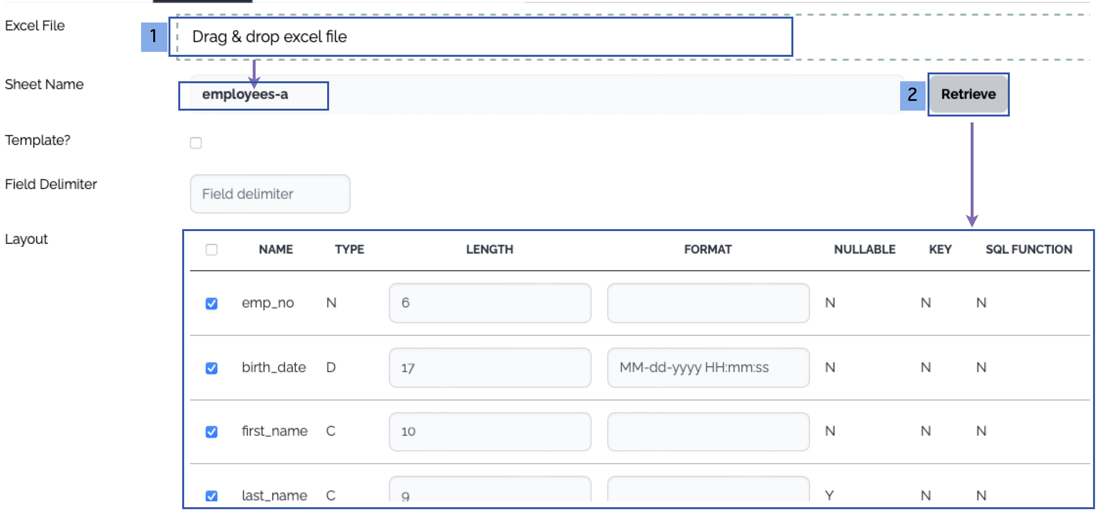
Drag and drop an excel file which contains data with header or a template excel file. The list of the sheets of the excel file is displayed.
Choose a sheet and click Retrieve button, then the columns are displayed. The first row is treated as the header - column names.

3. Target
Choose the target system and the operation
Choose or create a new target system just like the source system
Define the operation on the target data
Database
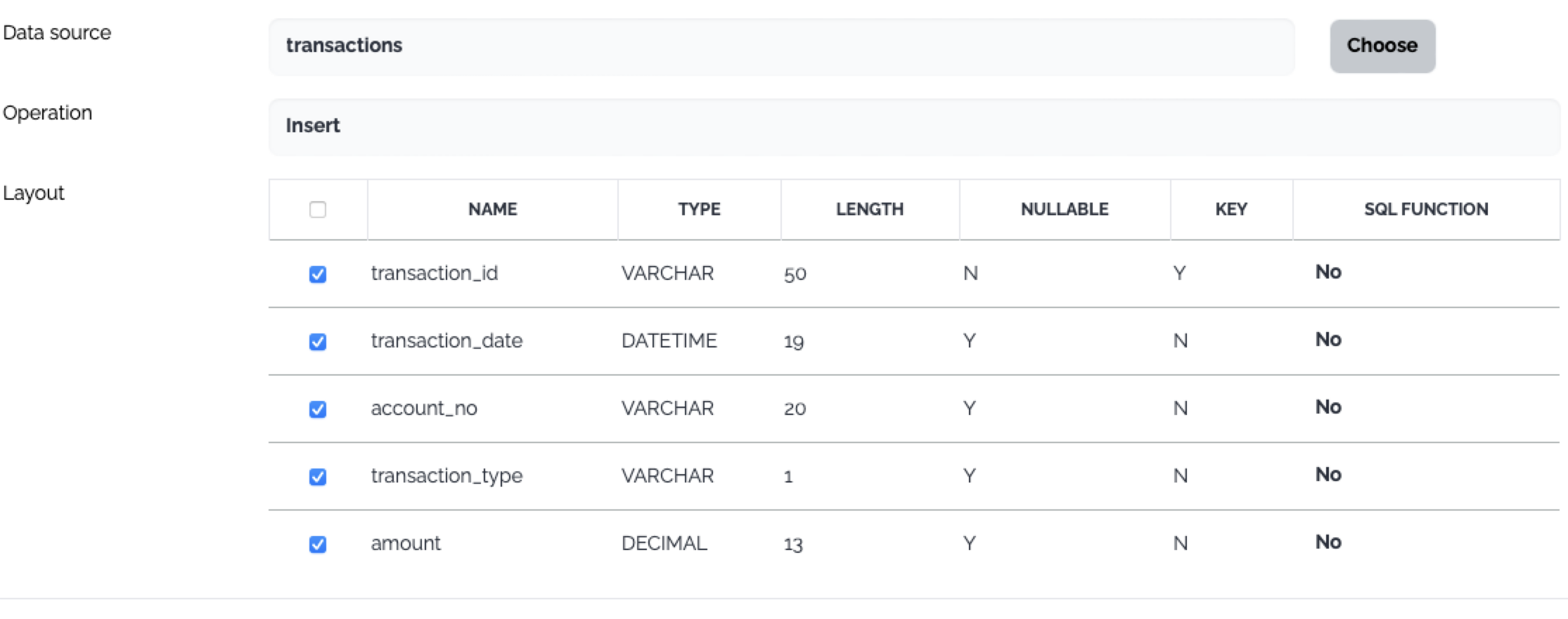
The operations on the target database do not use user provided query. There are predefined operations instead.
Insert
Update
Delete
Insert&Update
Update&Insert
Insert&Skip
Update&Skip
File
PropertyTypeDescriptionFile Path
Mandatory
The path of the target file - directory
File Name
Mandatory
The name of the target file.
Create Folders If Not Exist?
Mandatory
No - If the target folders does not exist, an exception is thrown.
Yes - If the target folders does not exist, the target folders are created
File Already Exist?
Mandatory
Skip - If the target file already exists, an exception is thrown.
Overwrite - If the target file already exists, the target file is overwritten.
Append - If the target file already exists, the source file or the contents are appended to the target file.
4. Mapping
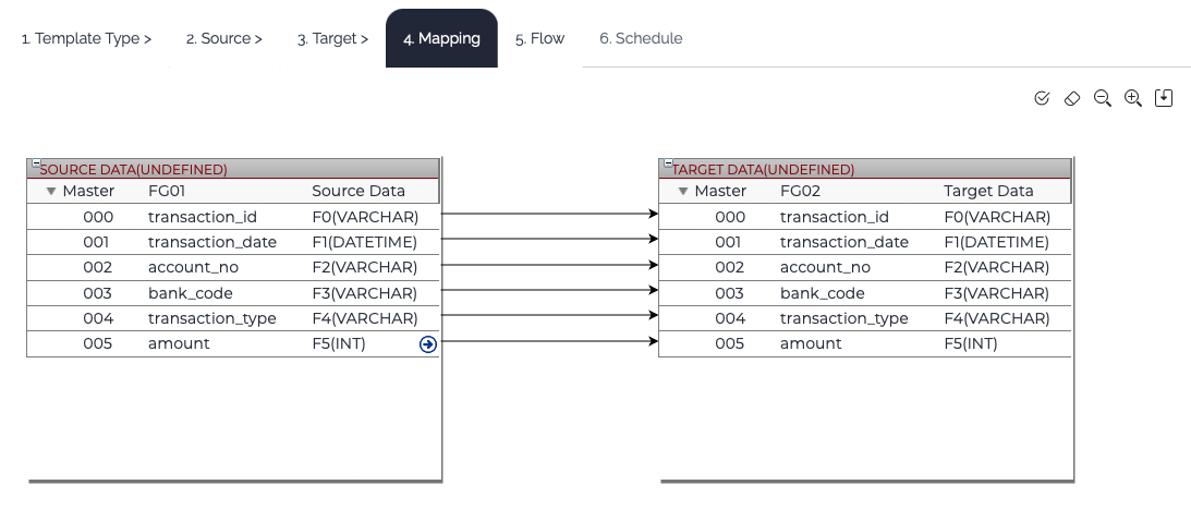
If the template type requires mapping, Mapping tab is enabled. Connect the input fields to the output fields. Refer to this link for the mapping in detail.
5. Flow
Enter the flow information. The properties of a flow in the template are not the full set of the properties. If you need further configuration, edit the generated flow manually later.
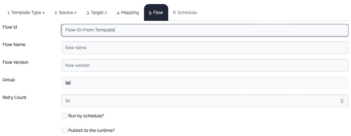
Flow ID
Mandatory
The id of the flow
Flow Name
Optional
The name of the flow
Flow Version
Optional
The version of the flow. If the version is empty, the default version name(v1) is assigned.
Group
Optional
The group of the flow
Retry Count
Optional
The retry count of the flow. The default value is 10.
Run by schedule?
Optional
If checked, The Schedule tab is enabled.
Publish to Rruntime?
Optional
If checked, all the items - data structure, system, flow - are published to the runtime.
6. Schedule
If this flow will be executed by scheduler, define the schedule. The properties provided in the template dialog are not the full set of the properties. If you need further configuration, edit the schedule later manually.
After all the configurations are complete, save the template.

Last updated